Pinout for the ESP8266 based Shelly Plug-S Smart Plug
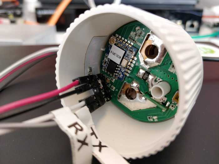
If you are like me and want the possibility to run custom firmware on your Shelly Plug-S, here's the pinout that makes it possible to easily program it!
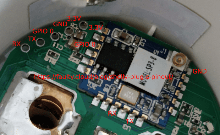
Looking at the main PCB from the top with the ESP module upwards, the programming pins are located in the rop right corner in the following order (bottom-left to top-right):
- RX
- TX
- GPIO0
- GND
- 3.3V
As usual for the ESP8266, GPIO0 must be grounded while applying power to enter programming mode. Also make sure that you connect RX on the board to TX on your 3.3V USB-TTL adapter, and TX on the board to RX on the adapter.
I use esptool.py to to flash the released Tasmota version onto the device. This way I don't need to care about setting up the environment to build Tasmota.
wall@box:~/$ esptool.py --port /dev/ttyUSB1 write_flash -fs 1MB -fm dout 0x0 sonoff.bin
esptool.py v2.1
Connecting....
Detecting chip type... ESP8266
Chip is ESP8266
Uploading stub...
Running stub...
Stub running...
Configuring flash size...
Compressed 519920 bytes to 355646...
Wrote 519920 bytes (355646 compressed) at 0x00000000 in 31.6 seconds (effective 131.6 kbit/s)...
Hash of data verified.

Leaving...
Hard resetting...
Configuring Tasmota to be a "BlitzWolf SHP Module" will make the power measuring, relay, button and LED's work. I have not yet looked into the over-temperature sensor that Shelly claims exists on board.

